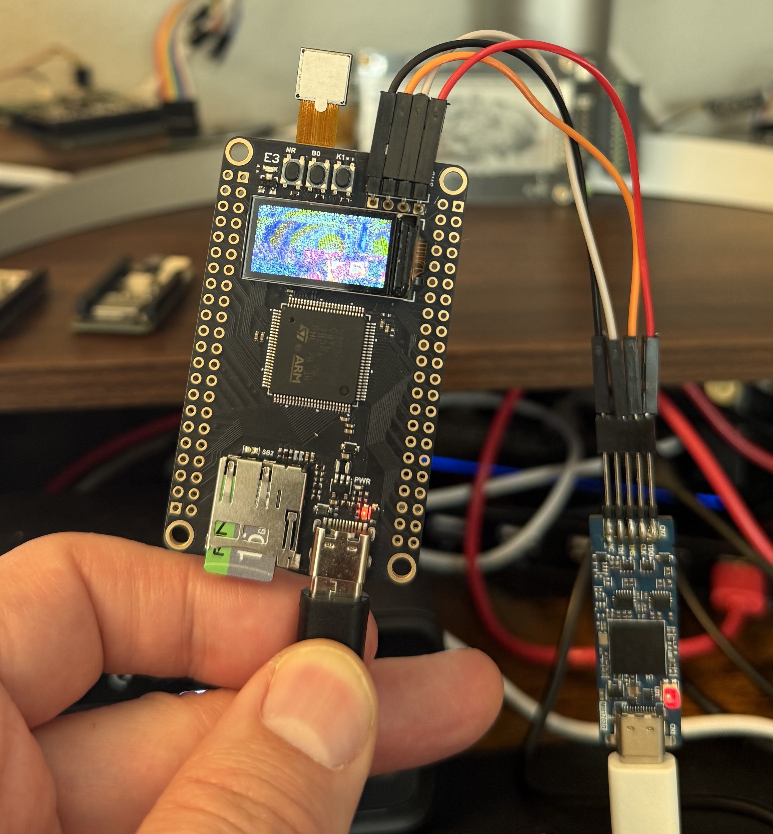
On paper, the WeAct Studio MiniSTM32H750VBTX looks like a dream development board. A powerful STM32H750 microcontroller, a built-in ST7735 display, and an OV2640 camera, all in a compact, affordable package.
What I thought would be a "simple weekend project" turned into a gritty saga of reverse-engineering electrical noise, fighting cache coherency, and wrestling with uninitialized ECC RAM. If you’ve ever bought a board based on raw specs only to find the documentation is a total black hole, pull up a chair. This one’s for you.
The Mission: A Real-Time Video Pipeline #
The objective was clear: build a high-speed video pipeline that captures frames from the OV2640 and slams them onto the LCD in real-time. To make this happen at a decent framerate, I had to bypass the CPU for the heavy lifting.
Here’s how the pipeline stages actually break down:
- OV2640 Camera: Outputs raw pixel data via an 8-bit parallel DVP bus.
- DCMI (Digital Camera Interface): The STM32 hardware peripheral that handles high-speed parallel capture.
- DMA (Direct Memory Access): Moves captured data into RAM with zero CPU intervention.
- RAM/CPU: Our "staging area" where we handle byte-swapping and color correction.
- SPI: The bottleneck. This pushes the processed data to the ST7735 display driver. Even with a 480MHz chip, the SPI bandwidth effectively caps our performance at ~15 FPS.
The Documentation Black Hole #
The first hurdle is always the paperwork, or the complete lack thereof.
The official repo provides some examples, like the DCMI to LCD demo, but they rely on STM32CubeIDE and don’t fully explain what’s going on.
- No Arduino support
- Minimal guidance for alternative ecosystems
- No clear “getting started” path
When the "official" tools failed, I pivoted to the Zephyr Project for reliable reference material. If you're tackling this board, don't guess, look at the source:
- Zephyr Mini STM32H7B0 documentation & source code
- Zephyr OV2640 Module documentation & source code
AI as a Co-Pilot (and Image-Based Debugging) #
To bridge the gap between "undocumented C snippets" and a modern "Rust-on-Hardware" implementation, I used Gemini and Claude as my digital Sherpas. Gemini was great at the grunt work, translating register-heavy C headers to Rust types. Claude acted as my code reviewer, spotting the kind of subtle logic flaws that lead to immediate HardFault exceptions.
My favorite "pro-tip" from this experiment? Image-based debugging. When the LCD showed nothing but "colorful sand" or psychedelic horizontal lines, I’d take a photo of the screen and upload it to the AI. Surprisingly, the models could look at the noise patterns and correctly identify byte-order mismatches or misaligned color formats faster than I could blink three times.
The War Stories: Technical Troubleshooting #
Getting this board to actually stream video was a series of battles against silicon quirks and architectural "gotchas."
Flash & Memory Constraints #
The STM32H750 is a high-performance part, but it only has 128KB of internal Flash. My compiled Rust binary exceeded this by 8.8KB almost immediately. The fix was a quick adjustment to Cargo.toml: setting opt-level = "s" for the dev profile. This optimized for size enough to squeeze the debug symbols in without overflowing the flash bank.
HardFaults and Alignment #
The program initially died during display initialization. The mipidsi crate performed a bounds check against the ST7735’s native 132x162 framebuffer. Because the example code was requesting 160x80, and 160 > 132, the driver panicked. The fix: Initialize at 80x160 (portrait) and apply a display_offset(26, 1) to center the logical canvas perfectly within the physical silicon.
Cache Coherency and ECC Hell #
This was the most brutal part. The Cortex-M7’s D-Cache and DMA do not play nice together. The CPU would try to clean the cache, but because the linker script was packing symbols and ignoring Rust's #[repr(align(32))], the start addresses truncated into physical uninitialized ECC RAM ranges. This instantly ripped open double-bit ECC faults, causing BusFault exceptions. The Fix: Bypassing the cache heuristics entirely. I used the MPU (Memory Protection Unit) to designate the SRAM4 region (0x3800_0000) as Non-Cacheable and Shareable (TEX=0, S=1, C=0, B=0). Crucially, I also had to explicitly zero the memory using FRAMEBUFFER.0.fill(0) to establish valid background ECC syndromes before the DMA ever touched it.
Power & Voltage Sags #
The LCD would frequently stay pitch black despite correct SPI signals. Initially, I tried clamping the camera reset (PA7) and power-down (PF1) pins, but this actually made things worse. Toggling these pins as outputs caused massive voltage sags on the 3.3V rail, crashing the LCD controller during boot. The Fix: Leave PA7 and PF1 floating (High-Z). The board’s native pull-ups handle the active states perfectly. Also, remember that on this WeAct module, the backlight pin (PE10) is Active-LOW. If you drive it HIGH, the screen stays dark.
Color & Frame Sync #
Once the data started flowing, I got the infamous "colorful sand" effect. The DCMI hardware packs 8-bit parallel sequences into 32-bit registers, which breaks 16-bit RGB565 pairings. A manual chunk.swap(0, 1) loop inside the framebuffer fixed the byte order. I also found a critical typo in the C-to-Rust register translation: the 0xDA Format Control register was set to 0x01 (YUV) instead of 0x08 (RGB565). Finally, to eliminate tearing, I polled the frame_ris bit in the DCMI status register to lock draw calls to the hardware VSYNC.
Final Performance & Results #
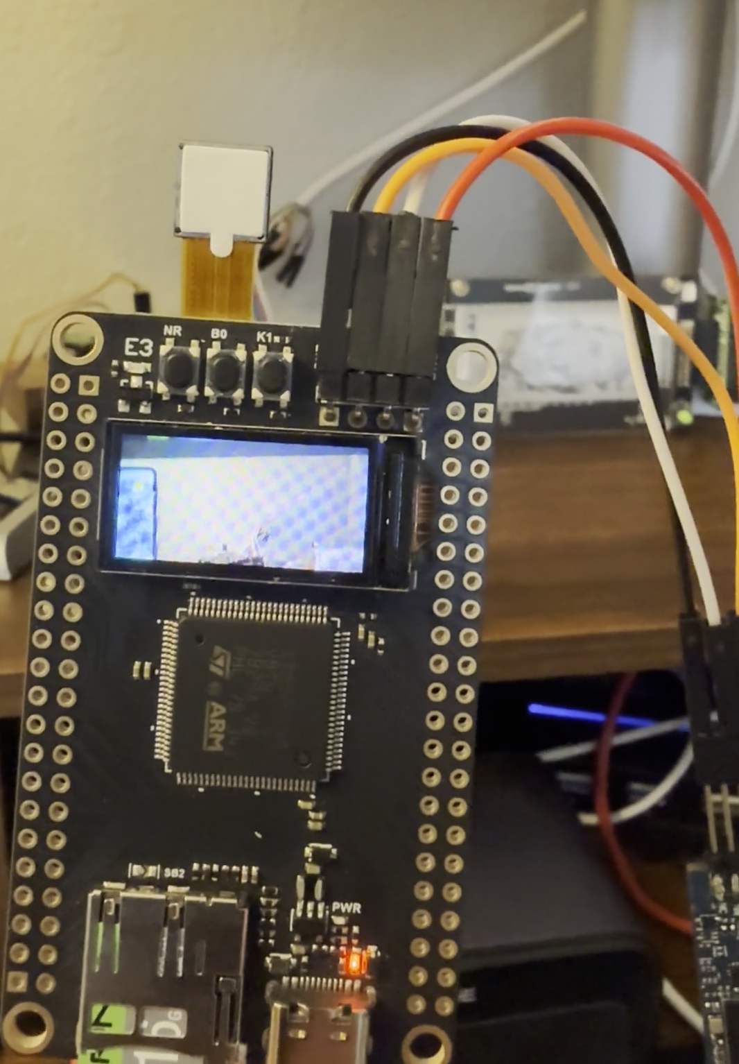
After hours of grinding, I have a stable, color-accurate video stream.
| Component | Main Issue | Final Resolution |
|---|---|---|
| Power | PA7/PF1 toggling caused sags | Leave camera GPIOs floating; use board pull-ups. |
| Clock | HSE instability | Reverted to 96MHz HSI for stable SPI/SysTick. |
| Memory | Cache incoherency / ECC Faults | MPU set SRAM4 to Non-Cacheable; zeroed RAM. |
| Backlight | Screen remained black | Drive PE10 LOW (Active-LOW polarity). |
| Colors | "Colorful Sand" / Wrong format | Manual chunk.swap(0,1) + Fixed Reg 0xDA. |
| Geometry | Image offset or clipping | 80x160 base + display_offset(26, 1). |
| Frame Sync | Heavy tearing/jitter | Polled DCMI frame_ris bit for VSYNC lock. |
Closing Thoughts #
The big takeaway? Cheap hardware is rarely actually cheap. You pay for the low price tag with your time, your sanity, and a lot of late-night datasheet reading. Documentation matters infinitely more than clock speed.
If you want to try this yourself (or just see the carnage), the full source code is available here.
Would I recommend this board? Only if you're a masochist who enjoys the specific "debugging hell" of undocumented registers and electrical noise. For everyone else: save yourself the headache and pay for a board with a real datasheet.