I'm Not a Graphic Designer, So I Vibe-Coded My Own Fritzing Parts
I write Rust drivers for e-paper displays. I do not own Illustrator, have never opened Illustrator, and have no intention of ever opening Illustrator. That turned out to be a problem, because I wanted to publish proper wiring diagrams for the two adapter boards I drive most of my panels through, Good Display's DESPI-C02 and Pervasive Displays' EXT3-1, and neither one exists in Fritzing's library. They're a little too niche.
The obvious fix is Fritzing's custom part editor: pick an existing part, clone it, redraw the board. I opened it, and Edit/Clone were greyed out. Turns out the editor needs an open sketch and a part actually placed on the canvas before it'll let you touch anything — not documented anywhere obvious, just a thing you're supposed to know. Fine. I got that far, looked at the drawing tools, and confirmed what I already suspected: I was not going to hand-draw a PCB silkscreen with a mouse.
The part that changed my mind #
Then I asked what a Fritzing part actually is, and the answer was the useful kind of anticlimactic: an .fzp file, which is just XML, plus up to four SVGs for the breadboard/schematic/PCB/icon views, zipped up as an .fzpz. No binary format, no proprietary editor required to produce one. I write YAML for a living, so writing XML by hand wasn't a stretch. I didn't need illustration skills. I needed a datasheet and a text editor.
I don't actually need the part to look real. I'm not laying out a PCB. All I need is a board-shaped rectangle with every pin broken out and correctly labeled, so I can drop it into a sketch next to my microcontroller and draw wires between the two. That's a much lower bar than "looks like the product photo" and it's one an LLM can clear without ever seeing a picture of the board: feed it the manufacturer's schematic PDF for the real pinout and it can write the SVG geometry directly.
So that's what I did: fed Claude Code the official DESPI-C02 schematic PDF and the wiring tables already sitting in my own repo's example files, and had it write the .fzp and SVGs by hand: literal <rect> and <circle> elements with coordinates in inches, no drawing tool in the loop at all.
Where it actually went sideways #
None of the friction was the XML. It was Fritzing's packaging conventions, which are true but not written down anywhere I could find:
- The file inside the
.fzpzarchive has to be namedpart.<something>.fzp. Get this wrong and Fritzing tells you flatly there's no part file, no hint about the naming rule. - The "folders" for the SVGs inside that archive aren't real zip directories. They're flat filenames with literal dots standing in for the path separators:
svg.breadboard.mypart_breadboard.svg, notsvg/breadboard/mypart_breadboard.svg. I only found this out by cracking open a working.fzpzI already had on disk and diffing its structure against mine. Nested folders import silently wrong: Fritzing happily installs the.fzpand just never finds any of the graphics. - Rotate a part in a sketch and any text baked into its SVG rotates with it — including labels you specifically drew to be readable. My first pass had pin labels that came out perfectly upright, then upside-down the moment the part got turned 90° to match how the board actually sits on a breadboard. Fix was to rotate the label text the opposite way in the source SVG so the two rotations cancel out in the one orientation I actually use.
None of these are hard problems. They're just undocumented ones, which is exactly the kind of thing that's fast to fix once you know it and slow to discover on your own.
Wiring diagrams, not just parts #
Once the adapter parts worked, I pushed further and asked for a full wiring sketch: Pico 2 on one side, adapter on the other, wires already drawn between the right pins. That meant computing real pixel coordinates for two different boards' connectors by hand: Fritzing places everything on a 90-units-per-inch canvas, a number I confirmed by reverse-engineering it from an existing sketch file's saved coordinates rather than trusting my own assumption. The math held up for eight of nine wires. The ninth landed two pins off, because the source part's SVG had layout quirks my extraction script didn't fully allow for. A five-second drag in the Fritzing UI fixed it. Good enough for a first draft; not something I'd trust unreviewed for a hundred-pin part.
What I ended up with #
Two adapter parts (plus 1.54" panel variants that glue a labeled display outline onto the same header, for anyone whose diagram needs to show a panel too), each with every pin correctly named from the manufacturer's own schematic, droppable straight into a sketch:
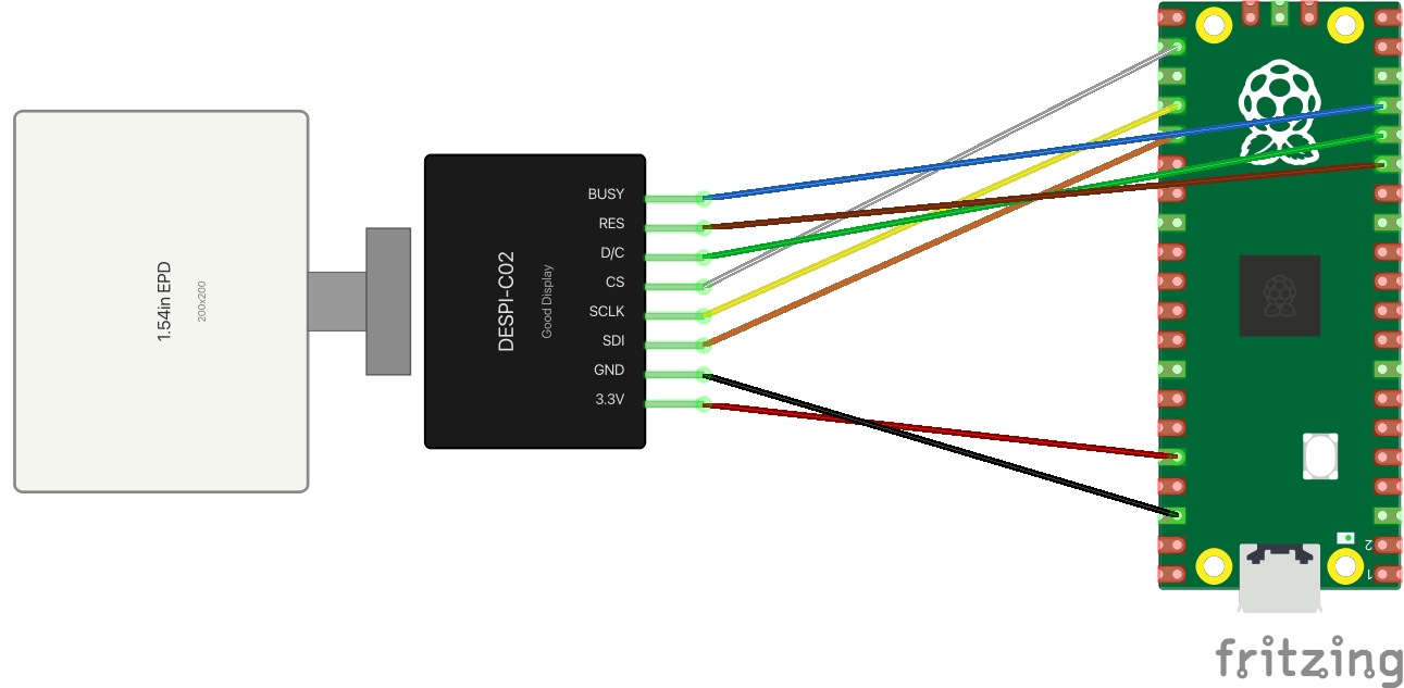
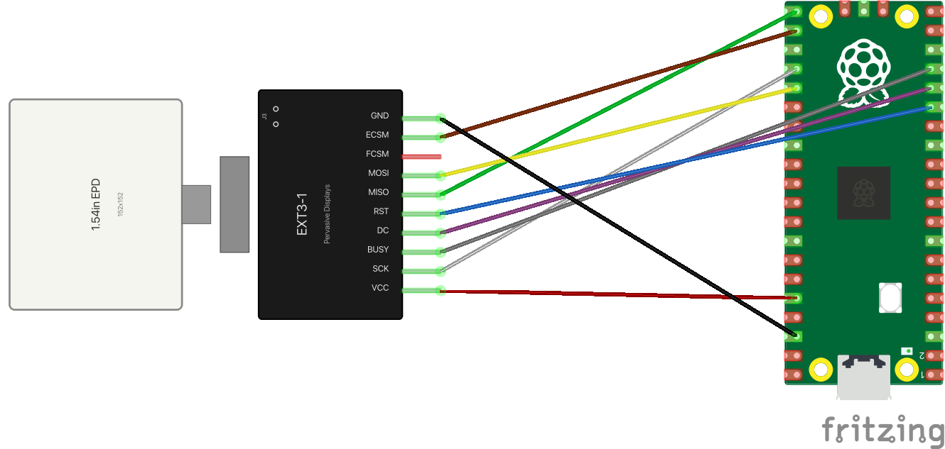
That second one uses the exact ribbon-cable colors from my own example code's wiring table: red for VCC, black for ground, the rest following the cable that actually ships in the kit. It's a small touch, but it means the diagram and the physical cable in front of you agree with each other at a glance, which is the entire point of drawing one.
The actual lesson #
I went looking for a way to draw a board and found a file format instead, which is the outcome I wanted without knowing it. I still can't use Illustrator, and for this I needed something else: it could read a PDF pinout table, write plain XML, and get corrected a dozen times without getting tired of it. An LLM with a terminal fits that job better than a graphic designer would. For parts this narrow ("just show me the pins"), that trade is a clear win.
The parts are in the fritzing/ folder of rust-rpico2-discovery if you're driving e-paper panels off either of these adapters and want a starting point instead of a blank canvas.